Digital AC Clamp and meter prototype
Concepts
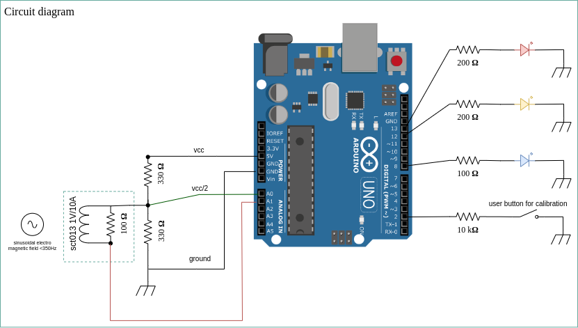
Sinusoidal currents inside electric cables produce a variable and also sinusoidal electromagnetic field. Thanks to the electrical induction pĥysical property, the sct013 sensor (a copper coil and a resistor in parallel) produces a voltage as output which is related to the fluctuations of the electromagnetic fields around the wire going through the sct013 clamp. As the arduino board has only capabilities to deal with positive analog inputs, a voltage divider circuit is used to raise the sinusoidal signal of the sct013 device.
Then, based on user frequency settings, the software will try to catch analog sample of data of exactly a period. It will then calculate min and max values over the period and the effective value of the sct013 output and then convert it into a current value (conversion ratio depend of sct013 model).
Final work consisted in energy accounting (kWh) and triggering amount of energy used (Wh) or money spent (€) in order to produce an action : the prototype produces a blue led flash.
Electronic design
The electronic design is very « pure » and simple.
A very small research with resistor values on the tension divider in order to meet as low consumption as possible and required stability of the output signal. It looked to me the tension divider resistors should be 3 times the sct013 device resistor value to meet my requirements.
Circuit limits
From 0 to 100mA of effective AC, the response of the sct013 device from 0 to 100mV within the circuit is not linear. A software correction is possible for this range.
Then, the Arduino circuit is 5V, centering the sinusoidal signal at 2.5V allows a max value of 2.5V also for the sinusoidal signal (1.76V effective). It means this circuit will only allow the following ranges of power, depending of the probe model :
- sct013 1V/10A: 0.1-17.6A
- sct013 1V/30A: 0.3-52.8A
- sct013 1V/60A: 0.6-105.6A
- sct013 1V/100A: 1-170A
VCC divider monitoring provides a good control for env changes like temperature, humidity, air pressure that can induce changes in electronic components. As the Arduino uno board has 6 analog port, 2 ports used per sct013 probe would limit to 3 probes max per board. Without vcc divider control we could double this number.
I have to mention I also tried monitor the ground line to gain more accuracy but I had unexpected noise that made this choice a complete wrong way. This would also mean a ground line monitored for all device. So only 2 sct013 probes max per Arduino UNO board.
Logs
The prototype produces also logs to the serial console. There is 4 level of logs (from 0 to 3). You can easily identify and change loglevel locating vars dedicated to this usage in the code :
static int LOG_LEVEL0=0;             // setup log level from 0 (no logs) to 3 (all required data)
static int LOG_LEVEL1=1;
static int LOG_LEVEL2=2;
static int LOG_LEVEL3=3;
Log Sample
Power Accounting and Triggering Engine v0.1 [08/11/2022 - freddy@linuxtribe.fr]
sct013::probe() WARNING device not calibrated()
sct013::probe() WARNING device not calibrated()
sct013::probe() WARNING device not calibrated()
sct013::probe() WARNING device not calibrated()
sct013::probe() WARNING device not calibrated()
sct013::probe() WARNING device not calibrated()
sct013::calibrate() calibration started, make sure the line is off
sct013 1V/10A (pin A5) [VCC divider: 2501.30mV (625.00pts) 50Hz:145.00pts] (25666.50-25659.18mV c=3.66mV) Amp 7.32mV UEff: 2.59mV [43 sample/sec] I=51.79mA
sct013 1V/10A (pin A5) [VCC divider: 2501.22mV (625.00pts) 50Hz:145.00pts] (25666.50-25659.18mV c=3.66mV) Amp 7.32mV UEff: 2.59mV [43 sample/sec] I=51.79mA
sct013 1V/10A (pin A5) [VCC divider: 2501.22mV (625.00pts) 50Hz:145.00pts] (25666.50-25661.62mV c=2.44mV) Amp 4.88mV UEff: 1.73mV [43 sample/sec] I=34.53mA
sct013 1V/10A (pin A5) [VCC divider: 2501.47mV (625.00pts) 50Hz:145.00pts] (25666.50-25659.18mV c=3.66mV) Amp 7.32mV UEff: 2.59mV [43 sample/sec] I=51.79mA
sct013 1V/10A (pin A5) [VCC divider: 2501.13mV (625.00pts) 50Hz:145.00pts] (25666.50-25659.18mV c=3.66mV) Amp 7.32mV UEff: 2.59mV [43 sample/sec] I=51.79mA
sct013 1V/10A (pin A5) [VCC divider: 2501.07mV (625.00pts) 50Hz:145.00pts] (25666.50-25659.18mV c=3.66mV) Amp 7.32mV UEff: 2.59mV [43 sample/sec] I=51.79mA
sct013 1V/10A (pin A5) [VCC divider: 2501.13mV (625.00pts) 50Hz:145.00pts] (25666.50-25659.18mV c=3.66mV) Amp 7.32mV UEff: 2.59mV [43 sample/sec] I=51.79mA
sct013 1V/10A (pin A5) [VCC divider: 2501.13mV (625.00pts) 50Hz:145.00pts] (25666.50-25661.62mV c=2.44mV) Amp 4.88mV UEff: 1.73mV [43 sample/sec] I=34.53mA
sct013 1V/10A (pin A5) [VCC divider: 2501.19mV (625.00pts) 50Hz:145.00pts] (25666.50-25659.18mV c=3.66mV) Amp 7.32mV UEff: 2.59mV [43 sample/sec] I=51.79mA
Calibration data : 47.34mA 8 pts.
Calibration ended : Ieff noise 47.34mA
EnergyCounter : 0.000004kWh (0.00000073€) Last=15.19W [24h a day : Max=0.36kWh avg=0.18kWh]
EnergyCounter : 0.000015kWh (0.00000257€) Last=37.98W [24h a day : Max=0.91kWh avg=0.46kWh]
EnergyCounter : 0.000025kWh (0.00000441€) Last=37.98W [24h a day : Max=0.91kWh avg=0.68kWh]
Capabilities
Autocalibration process end-user can launch any time (yellow led)
SCT013 Vcc divider monitoring
Freq range : 0-300Hz (only 50Hz has been seriously tested). At 50Hz, hardware is capable analyse 45 periods over 50 a second.
Analog sample recording over a period (1/freq) with timestamp of micro second resolution (oscilloscope capability).
Detect power on the line (red led)
Count user-defined energy amount (in Wh) or bill amount (blue led)
Software limits
As this project is a prototype, the code has not been design to handle correctly end of timer() when millis() or micros() will reach its max value and start back from zero.
The code would need to be optimized in many cases or reviewed. I miss advanced c/c++ skills to take max advantage of the compiler and the hardware.
The prototype finally use a calibration() process to read the electromagnetic noise it reads from the probe when the monitored power line is down. Then, any read value bellow 110% of the noise value will be considered as « noise », and the prototype will not include this data in the energy accounting process (the noise the circuit read when the power line is off looked to be related to the DC supply used with the Arduino board in my case).
Code architecture overview
The code uses 4 custom object classes :
// time operations
class timer {
 public:
     timer(bool _micro=false);
     void reset(void);
     float duration(convert _c=none);
     String report(convert _c=none, int _digits=0);
};
// analog sample record and processing
class analogSample {
 public:
     analogSample(int _freq, int _divider_pin, int _device_pin);
     void readDividerValue(void);
     void resetSample(void);
     void readSample(void);
     void processSample(int _log_level);
     double getUEff(void);
     void report(void);
};
// sct013 device object with calibration
class sct013 {
 public:
   int devicePin;
   int deviceModel;
   bool calibrated;
   sct013(int _vcc_divider_pin, int _device_pin, int _device_model);
   void calibrate(int _length, int _freq, int _log_level=0);
   double probe(int _freq, int _log_level=0, bool _calibrate=false);
};
// energy accounting (and billing) and trigger settings
class EnergyMonitor {
   EnergyMonitor(int _voltage, int _freq);
   double getPower(sct013 _device, int _log_level=0);
   double getPowerCount(int _log_level=0);
   double getBudget(float _kWh_cost=0.1740);
   void setupLeds(int _cLed, int _pLed, int _wLed, int _wStep);
   void updateLeds(sct013 _device);
};
User settings may be changed just before setup() function :
static int POWER_FREQ=50;   // setup your electrical network frequency
static int POWER_VOLTAGE=220; // setup your electrical network voltage for power accounting
static float POWER_ACCOUNTING=1; // setup power accounting in Wh in   order wLed to report
static int SCT013_CALIB_TIMEOUT=10000; // setup timeout for sct013 devices to calibrate
Then you’ll probably need to read more of the code to setup as you need accounting, money conversion and thresholds to trigger an event and get the blue led flash or anything else with an external device you can drive from the Arduino board.
This article has also been published on Arduino project hub portal and on hackster.io :
https://projecthub.arduino.cc/ffrouin/digital-ac-clamp-and-meter-prototype-bcd17d
https://www.hackster.io/ffrouin/digital-ac-clamp-and-meter-prototype-a753ec
https://www.hackster.io/ffrouin/accm-shields-v1-v2-for-arduino-uno-2a29a2